Testing & Materials
Steel C-Channel Beam Deflection Analysis
Project overview
Measured Deflection Versus Beam Theory.
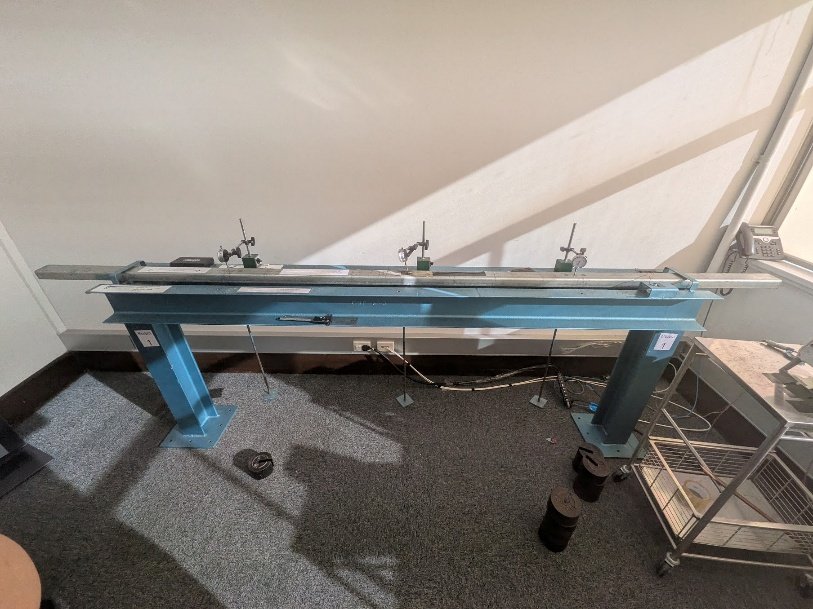
I loaded a simply supported steel C-channel off-center, measured how far it deflected, and checked the results against deflection equations I derived.
The beam was loaded at Hook 1 (a = 468 mm from the left support) in 10 lb (44.5 N) steps up to 222.5 N and back down, with dial gauges at Hook 1 and near midspan at Hook 2 (z ≈ 1228 mm).
Key Work & Outcomes
- Measured peak deflections of 1.38 mm at Hook 1 and 1.99 mm at Hook 2 under the 222.5 N maximum load.
- Showed a linear load-deflection response (R2 ≥ 0.998) with full elastic recovery on unloading.
- Predicted every deflection within 10% of measurement (maximum 9.01% at Hook 1 and 9.77% at Hook 2).
- Derived closed-form deflection and bending-moment expressions and rounded-corner section properties.
In the lab
Setting Up And Measuring The Beam
Accurate predictions start with accurate dimensions.
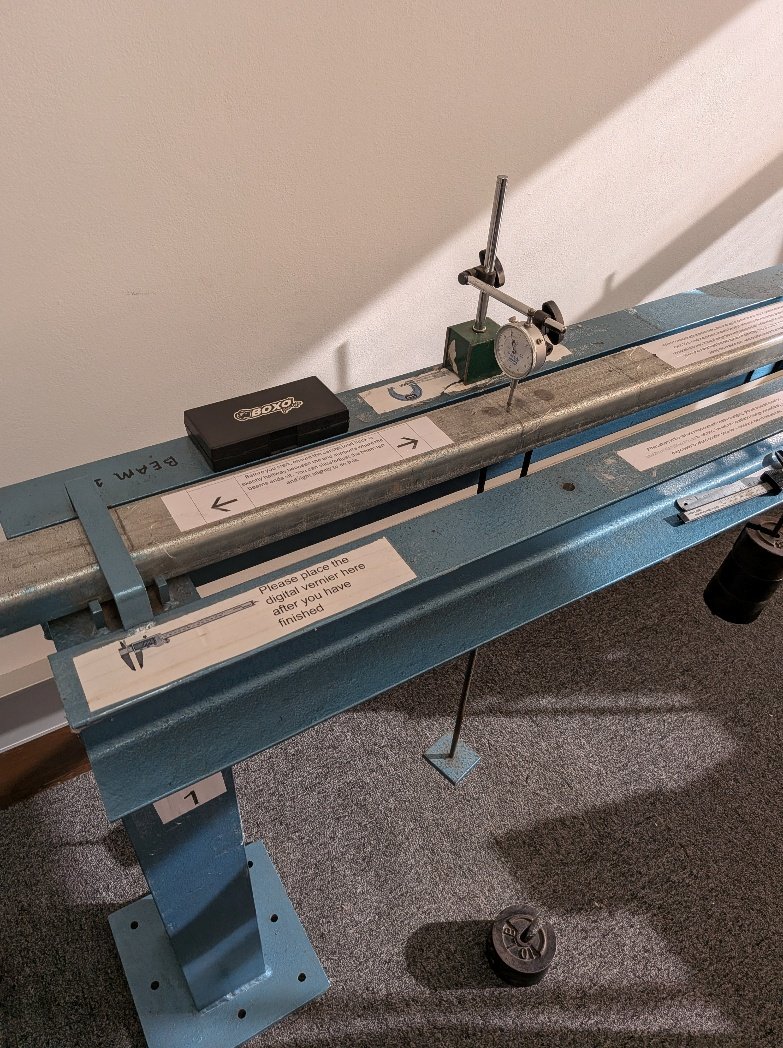
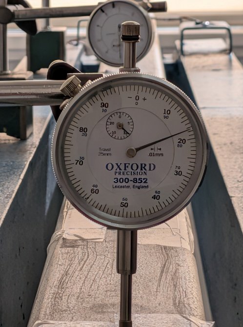
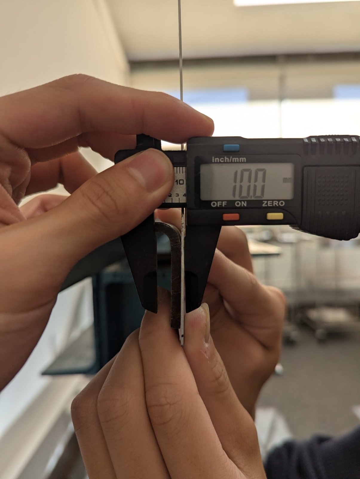
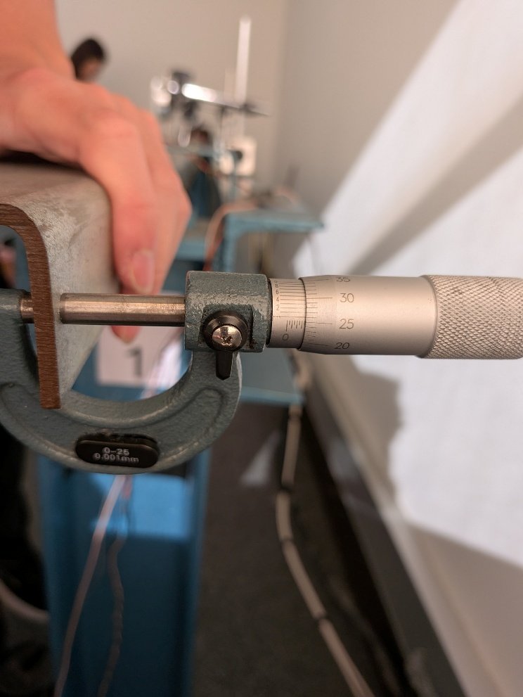
I measured the channel’s depth, flange width, and corner radius with a vernier and ruler, and its wall thickness with a micrometer, on both ends of the beam. Dial gauges were set vertical and zeroed before each loading sequence.
Analysis
From Cross-Section To Deflection Curve
Rounded corners change the stiffness only slightly, but the theory has to account for them.
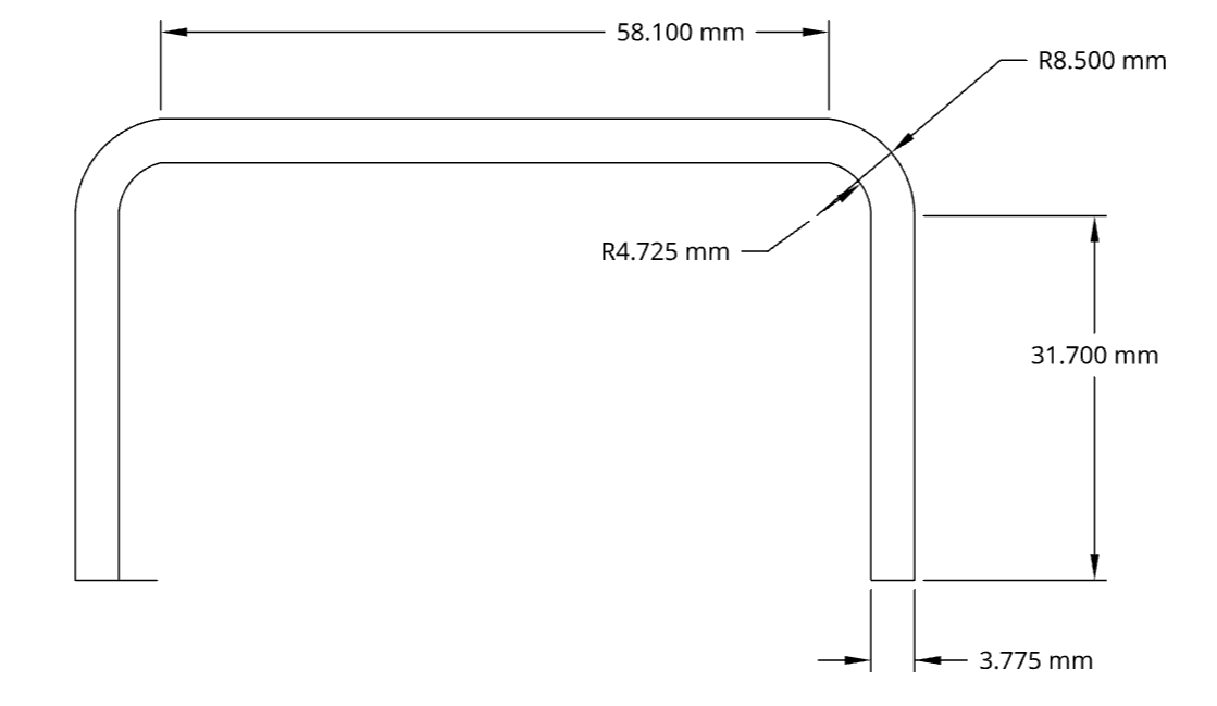
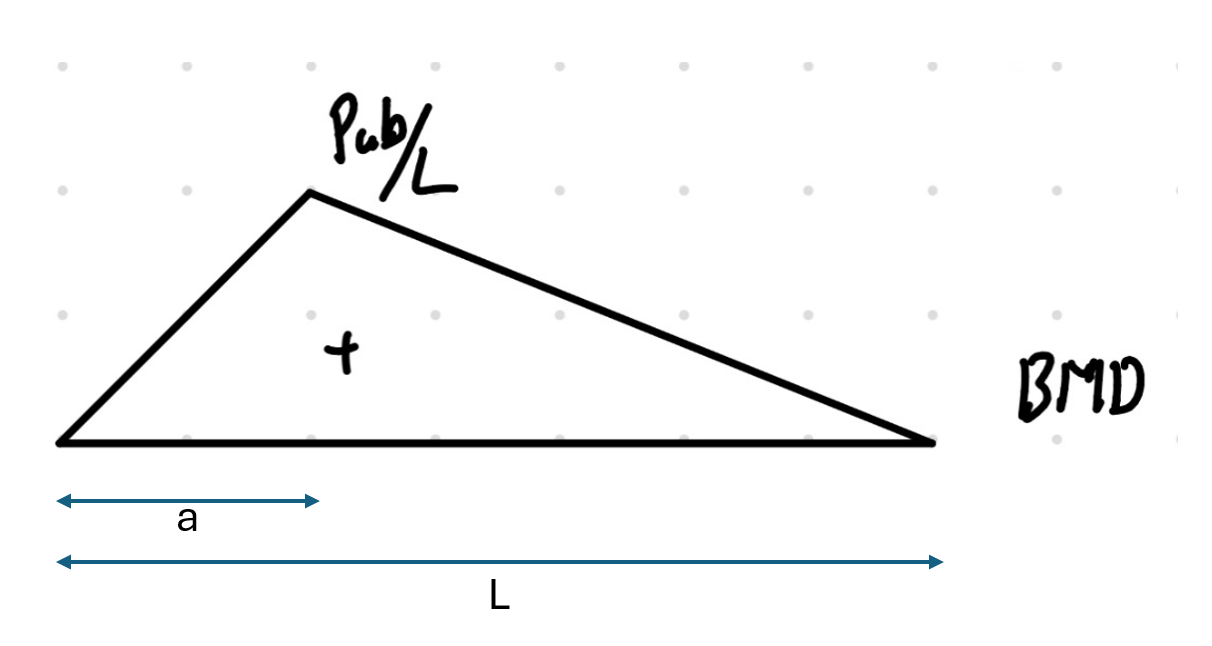
I calculated the second moment of area twice: once for an idealized square-cornered section and once for the real section, splitting it into flanges, web, and two quarter-annulus corners and deriving the corner inertia with the parallel axis theorem. From the bending moment diagram and the support boundary conditions, I derived the deflection equation for a point load at any position along the span.
| Section model | Centroid ȳ | Second moment of area Ix |
|---|---|---|
| Square corners | 28.42 mm | 0.0871 × 106 mm4 |
| Rounded corners | 27.97 mm | 0.0844 × 106 mm4 |
Continue exploring