Design & Fabrication
2.5 DoF Carnival Fishing
Project overview
A Joystick-Controlled Carnival Fishing Game.
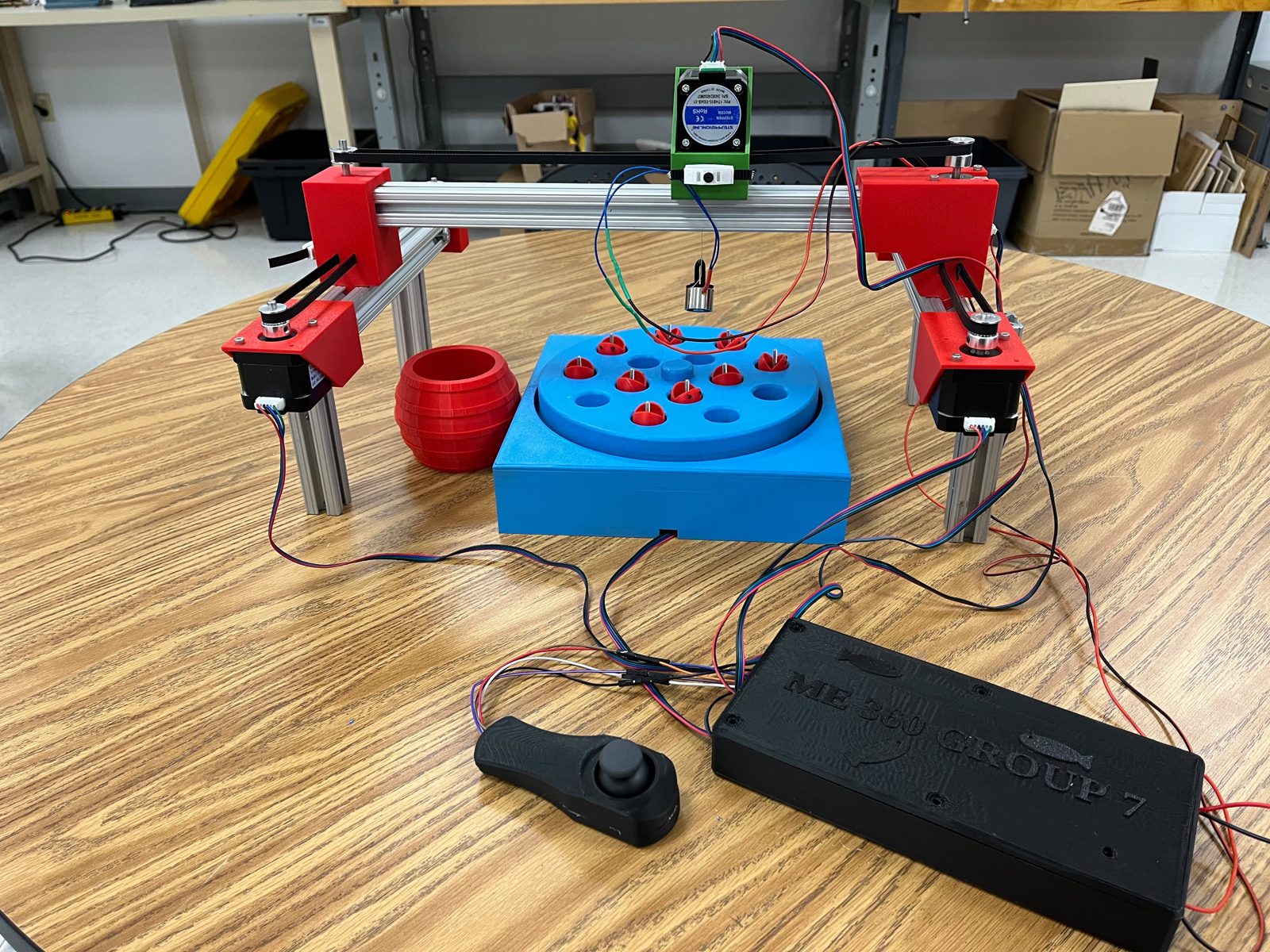
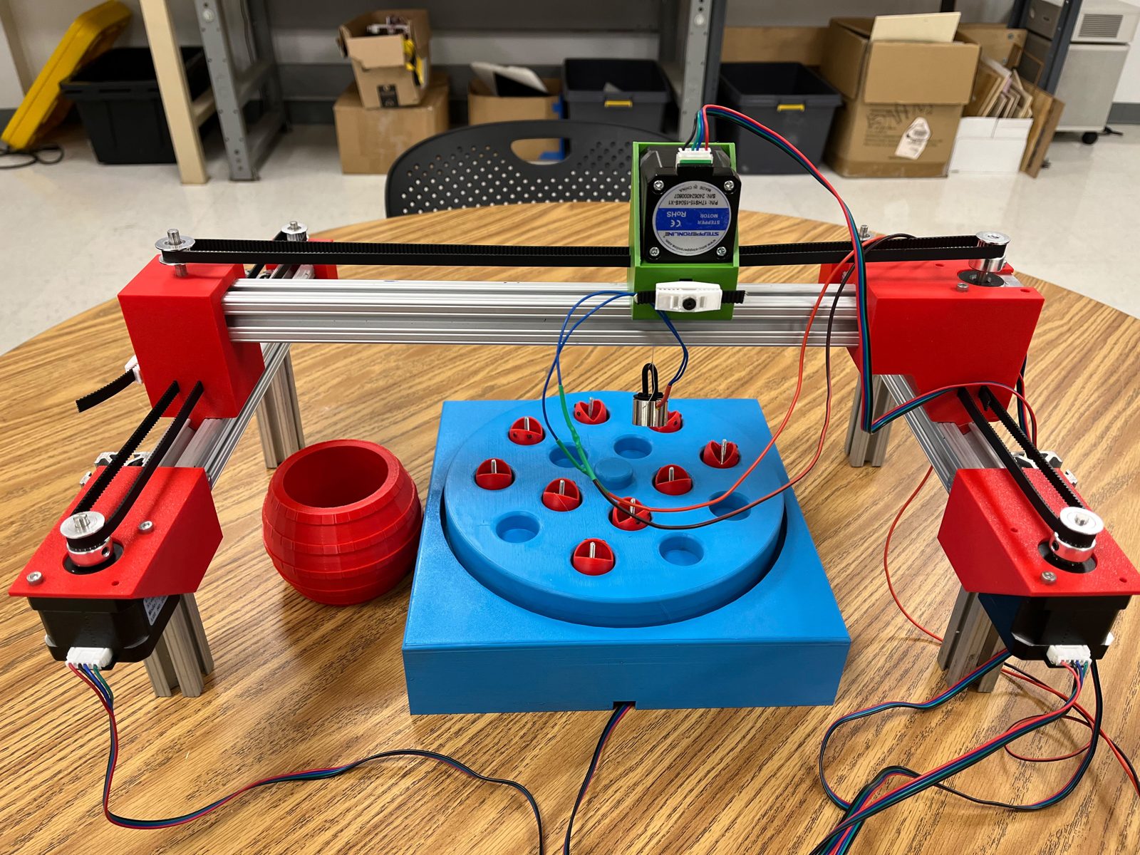
Our team built a 2.5-degree-of-freedom gantry that turns the carnival fishing game into a machine: the player steers an electromagnet over a spinning plate of fish with a joystick, dips it to pick a fish up, and drops it in the bucket.
The gantry moves freely in X and Y, which gives two full degrees of freedom. The third axis, Z, only has two positions, up and down: one press of the joystick lowers the magnet, pauses, and lifts it back up. That limited vertical motion is the “half” degree of freedom. A fifth stepper motor spins the plate underneath to make the game harder, and everything runs from one handheld joystick and one control board.
This page follows the project in order: the brief, how it plays, the first linear stage, the CAD models, each part as built, manufacturing, electronics and code, and the final assembly.
Key Work & Outcomes
- Demonstrated the working game to our professor, who played it with the joystick.
- Built a belt-driven gantry on 80/20 aluminum extrusion with X–Y travel of up to 50 mm/s and a 10 mm Z dip.
- Designed a purpose-built end effector: a printed holder that carries an electromagnet, plus 3D-printed fish with steel screws for it to grab.
- Drove five stepper motors (two for X, plus Y, Z, and the plate) and the electromagnet from one MKS Base board.
- Wrote Arduino firmware over seven versions that maps one joystick to movement, the Z dip, the magnet, and a three-round game.
- Modeled every printed part in SolidWorks, with equation-driven motor mounts sized from the NEMA 17 dimensions.
The brief
A Portable Motion System With A Purpose
In six weeks, each team had to design, build, and integrate a Cartesian motion system that performs a task of its choice.
| Requirement | How it shaped our design |
|---|---|
| End effector work area of at least 2.5 in × 2.5 in | The gantry spans the whole fish plate, so the magnet can reach every pocket |
| Small and light enough to carry in a backpack; assembled by one person in 10 minutes | A frame of stock 80/20 lengths joined by printed blocks and screws |
| Provided extrusion, stepper motors, belts, and pulleys | The extrusion doubles as the frame and the linear guide for each axis |
| All other parts 3D printed or laser cut, joined with standard fasteners (no tape or glue) | Every custom part was 3D printed and fastened with screws |
| Extra credit for an original, purpose-built end effector | An electromagnet holder that picks up fish carrying steel screws |
How it plays
One Joystick, Four Actions
The player lines the magnet up over a fish, switches the magnet on, dips to pick the fish up, and carries it to the bucket.
Pushing the stick further moves the gantry faster, so small corrections are easy and long moves are quick. While the magnet is dipping, X and Y are locked so the player can’t drag the magnet sideways through the fish.
| Joystick input | What the machine does |
|---|---|
| Push the stick | Moves the magnet in X and Y; speed follows how far the stick is pushed |
| Press once | Z dips down 10 mm, pauses for 0.3 s, and comes back up |
| Press twice quickly | Turns the electromagnet on or off |
| Hold for 0.8 s | Starts the plate game, or stops it early |
The plate game gets harder each round, with a 3-second pause between rounds:
| Round | Length | Plate motion |
|---|---|---|
| Round 1 | 60 s | One turn every 4 s |
| Round 2 | 45 s | Twice as fast (one turn every 2 s), in the opposite direction |
| Round 3 | 60 s | Split into 2–4 random parts; every part reverses direction at a new random speed |
First linear stage
Starting With One Axis
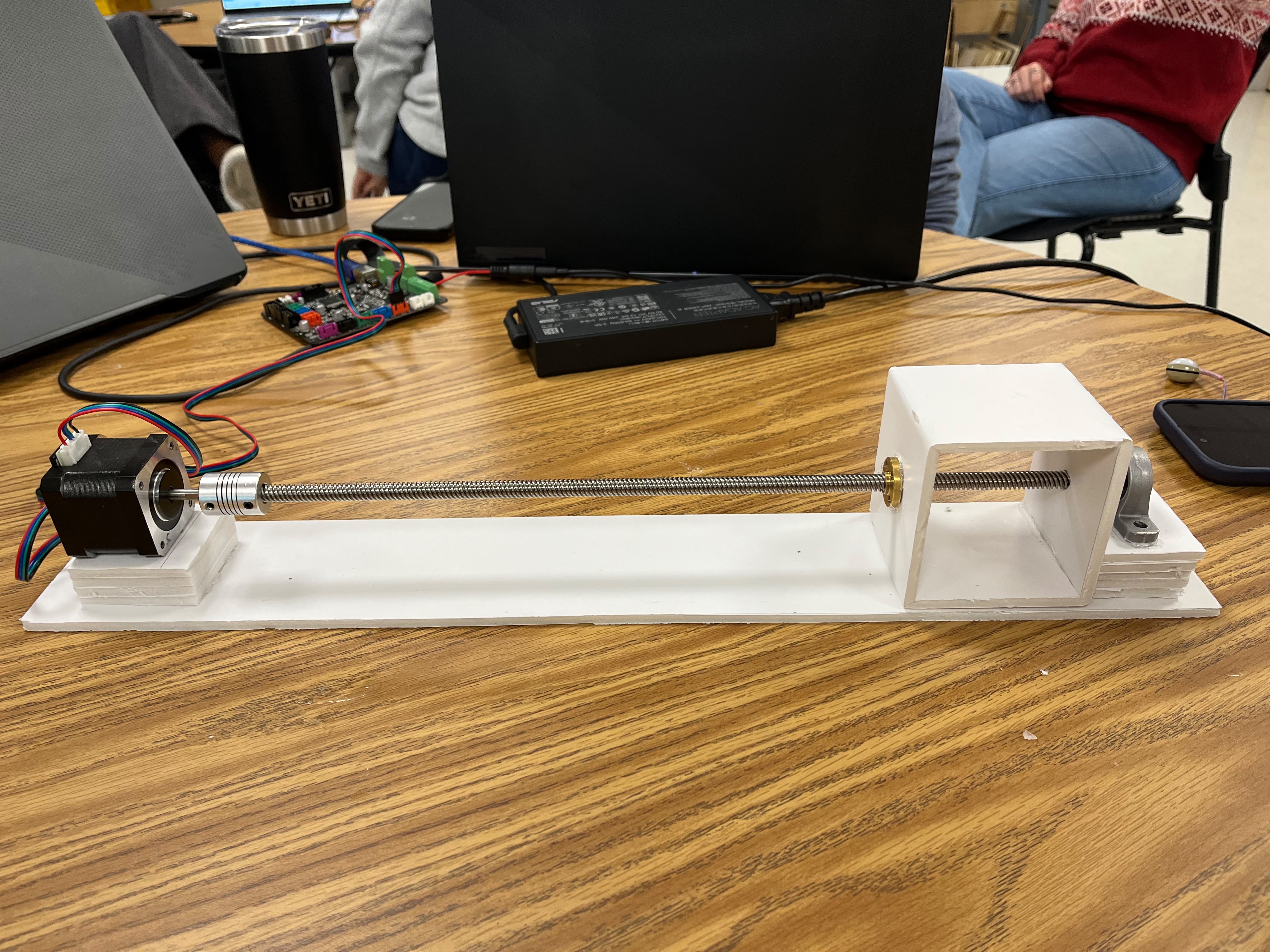
Before designing the gantry, we built and tested a single linear stage.
The first stage used a NEMA 17 stepper turning a lead screw through a flexible coupler. A brass nut drove a foam-board carriage along the screw, with a pillow-block bearing supporting the far end. We drove it with G-code through Marlin firmware, configured at 400 steps/mm for the 8 mm-per-turn lead screw, then stacked two stages into the in-class plotter.
For the fishing game, we kept the NEMA 17 motors and the MKS Base board but switched to timing belts running on 80/20 aluminum extrusion. Belts move a carriage much faster than a lead screw, which a game needs, and the extrusion serves as both the frame and the rail.
CAD models
Designed In SolidWorks
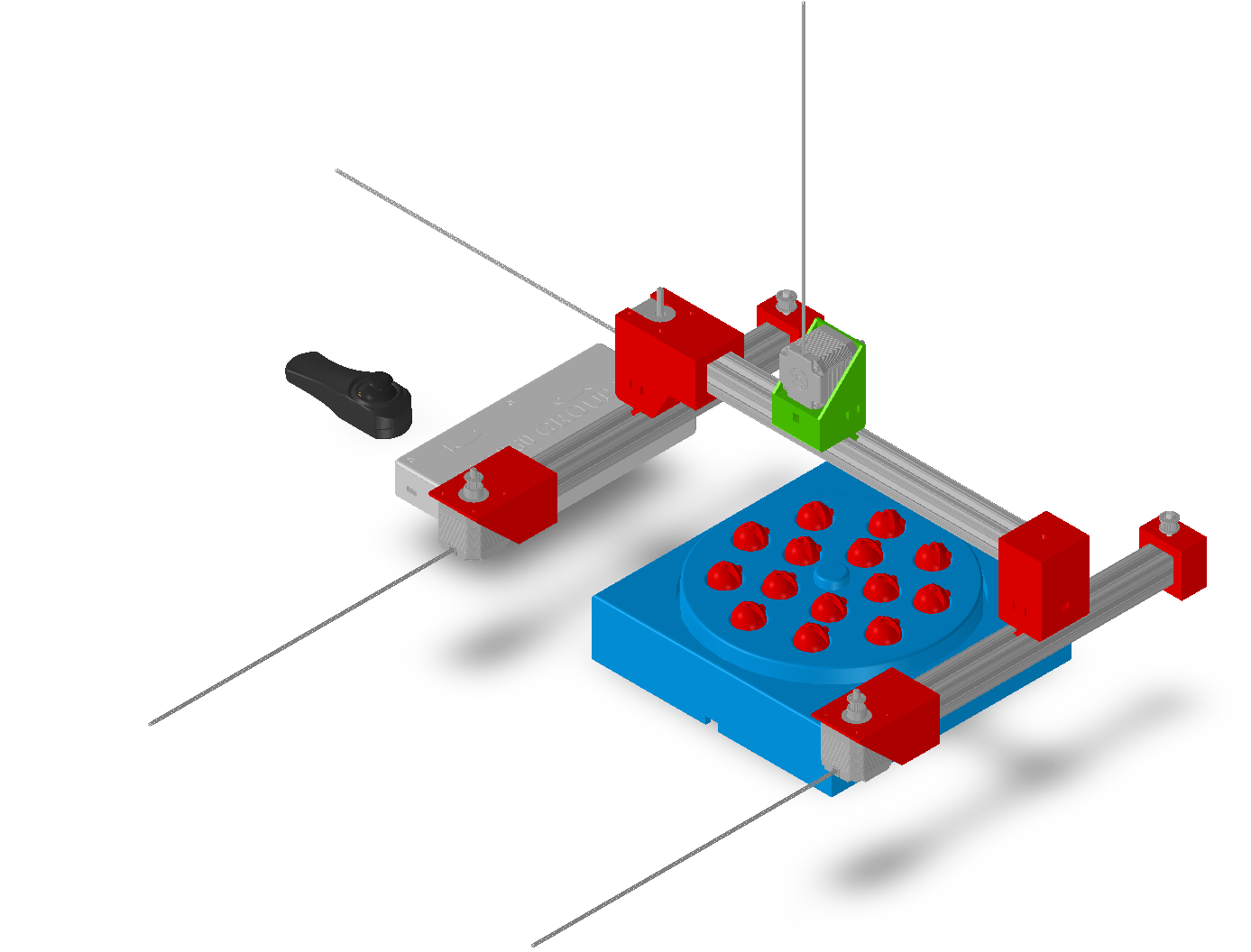
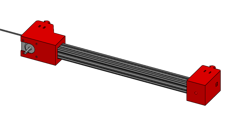
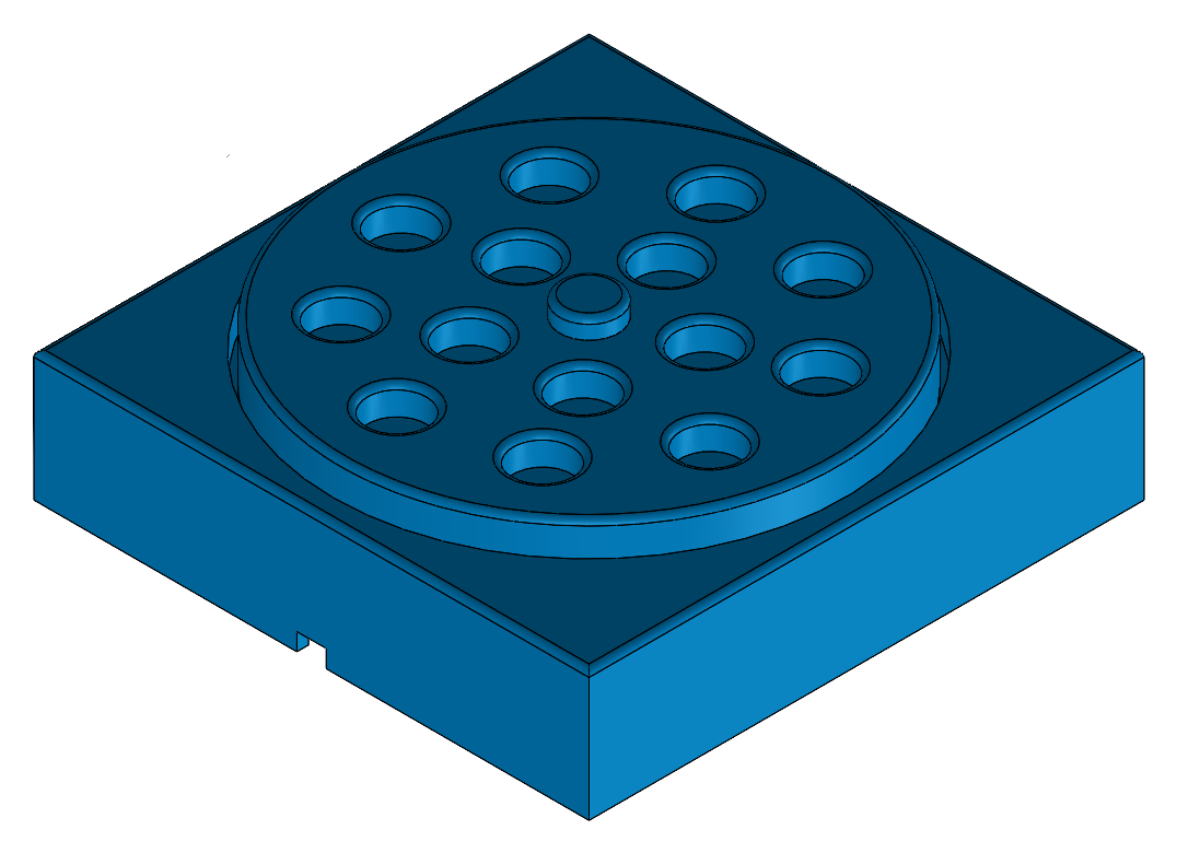
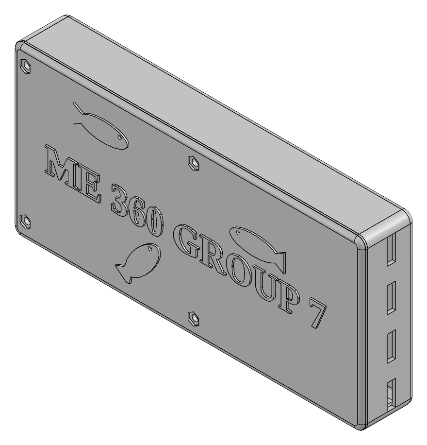
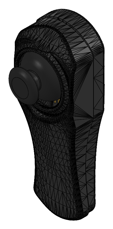
The whole machine was modeled as one SolidWorks assembly, built up from subassemblies for each axis, the plate, and the controls.
We imported vendor models of the NEMA 17 motors, timing pulleys, MKS Base board, and joystick module to check fit and clearances. The motor mounts are driven by global equations (a 1.7 in motor face, 1.2205 in between mounting holes, a 5 mm shaft, and the 1 in extrusion size), so changing one number updates every mount.
Part by part
Every Printed Part, In CAD And As Built
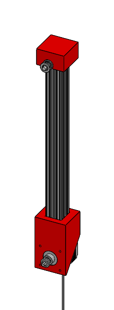
Each custom part was designed around the 1 in extrusion, the NEMA 17 motors, or the game itself.
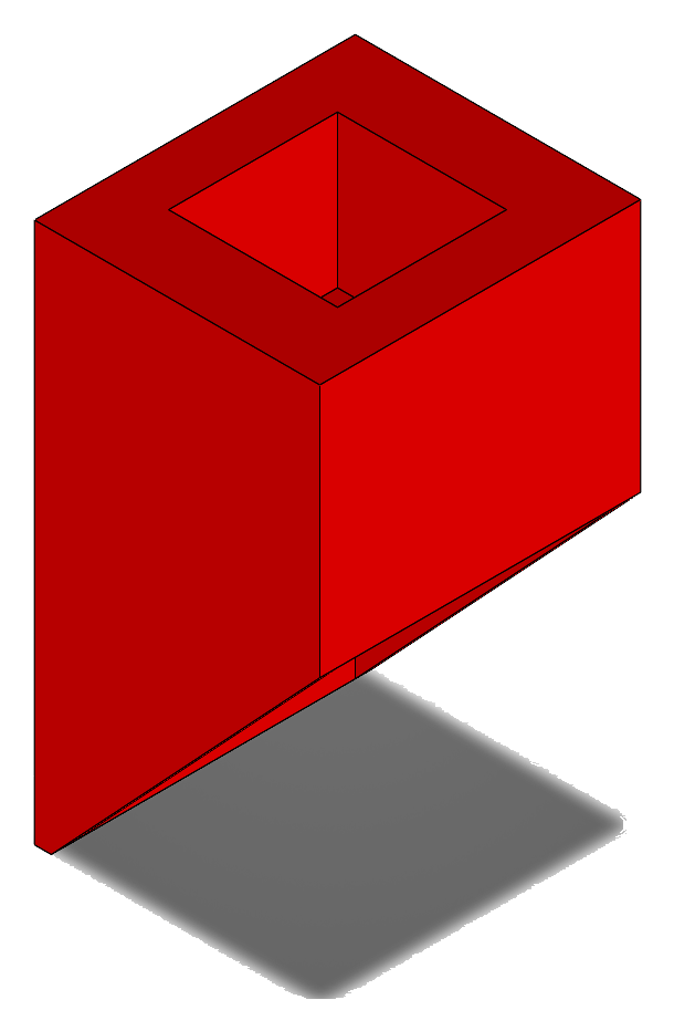
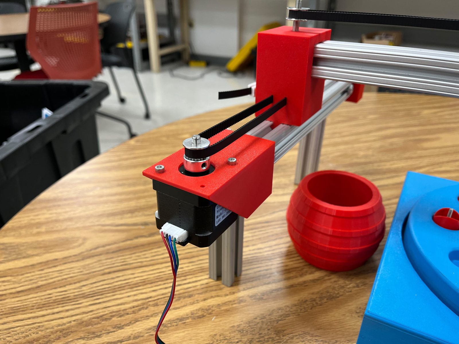
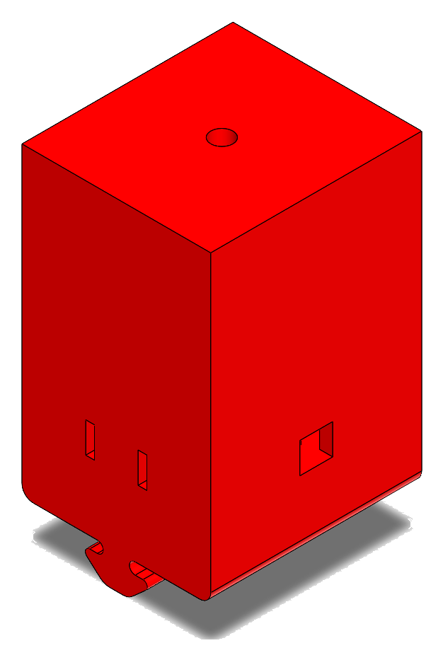
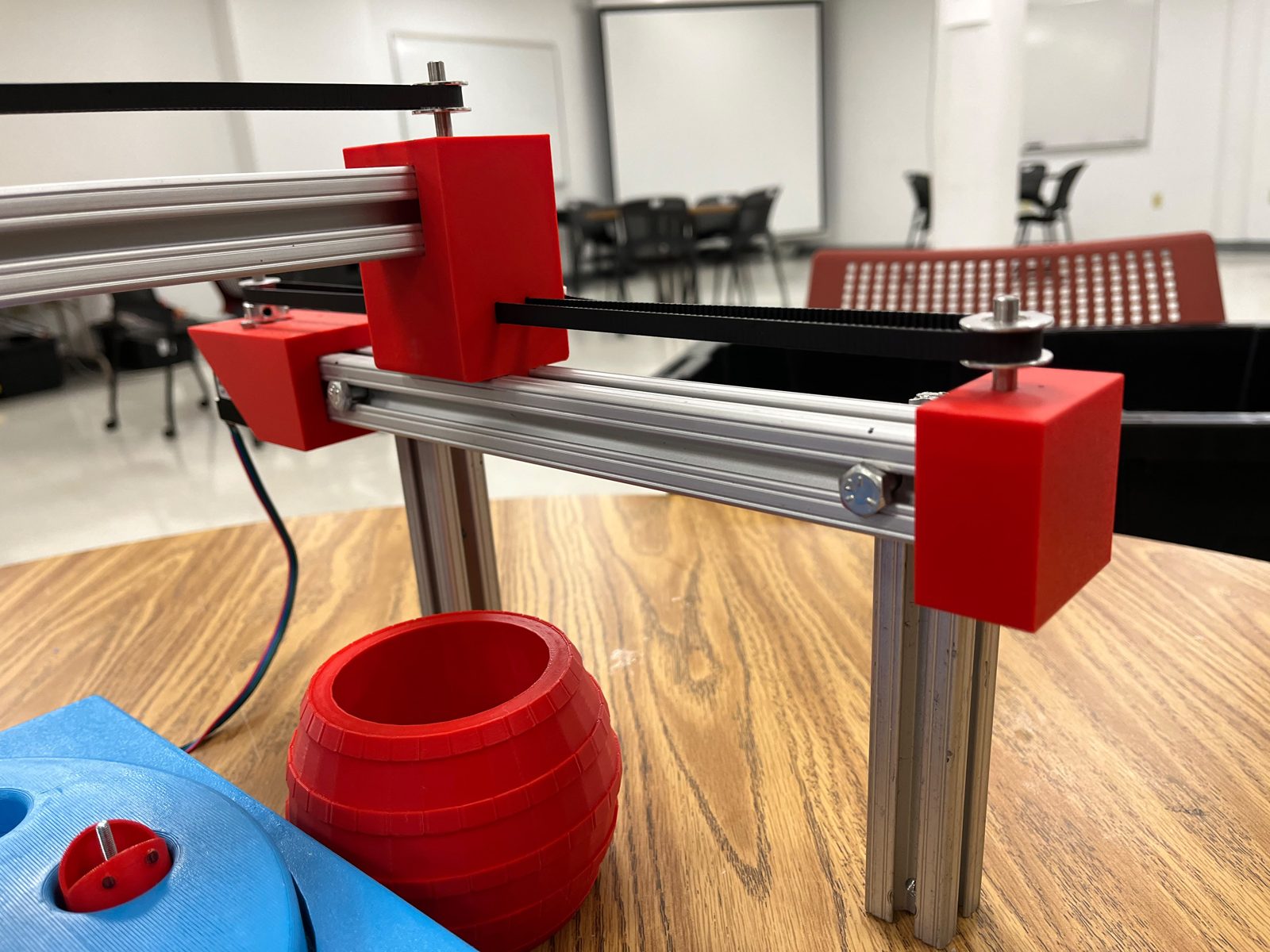
| Part | What it does |
|---|---|
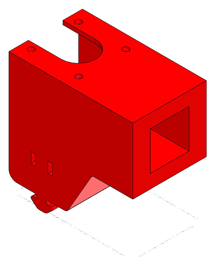
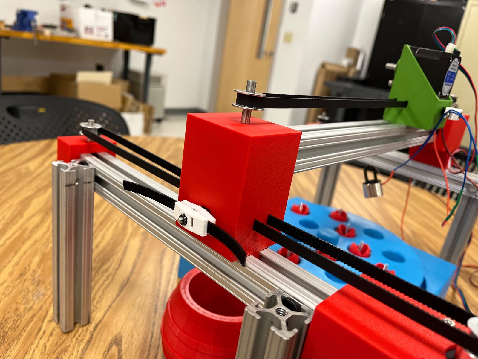
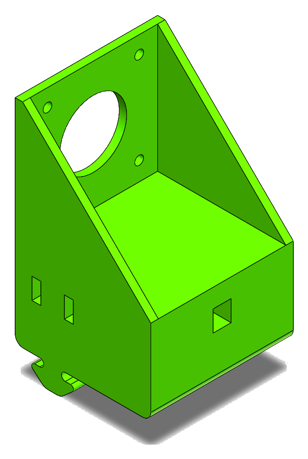
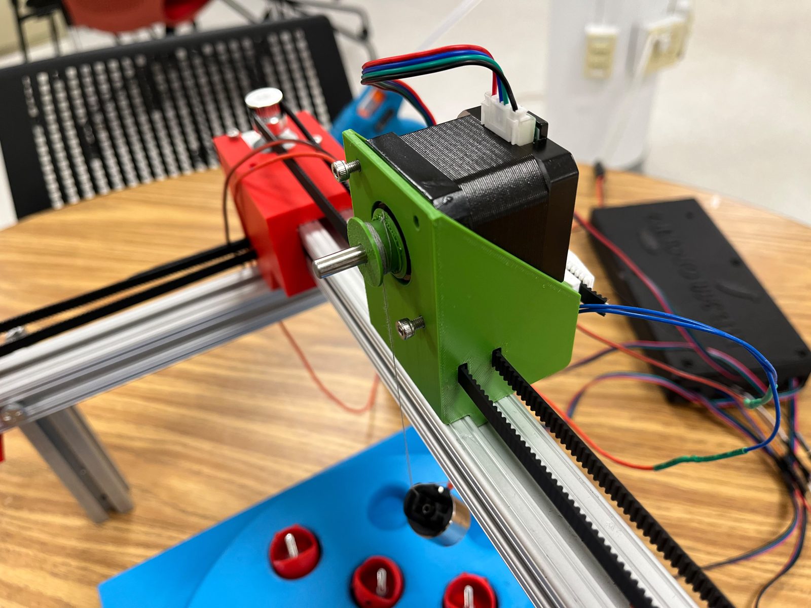
| Motor holder | Clamps a NEMA 17 under the end of an X rail; the pulley on top drives that rail’s belt |
| Rail end block | Closes the other end of each rail and carries the idler pulley the belt wraps around |
| X carriage | Slides along an X rail on the extrusion and holds one end of the Y rail |
| 8020 holder | Joins lengths of extrusion where the frame meets |
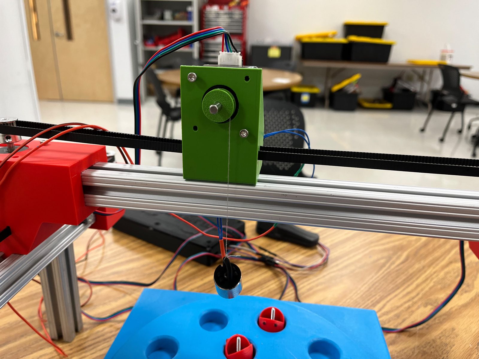
| Z motor holder | Rides along the Y rail and carries the Z motor that raises and lowers the magnet |
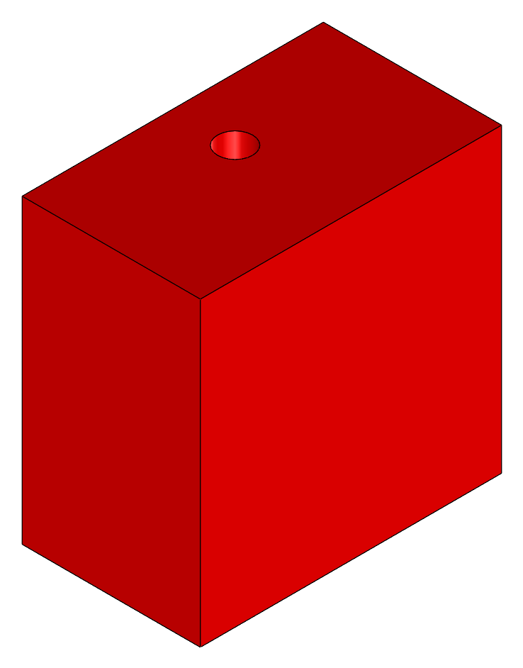
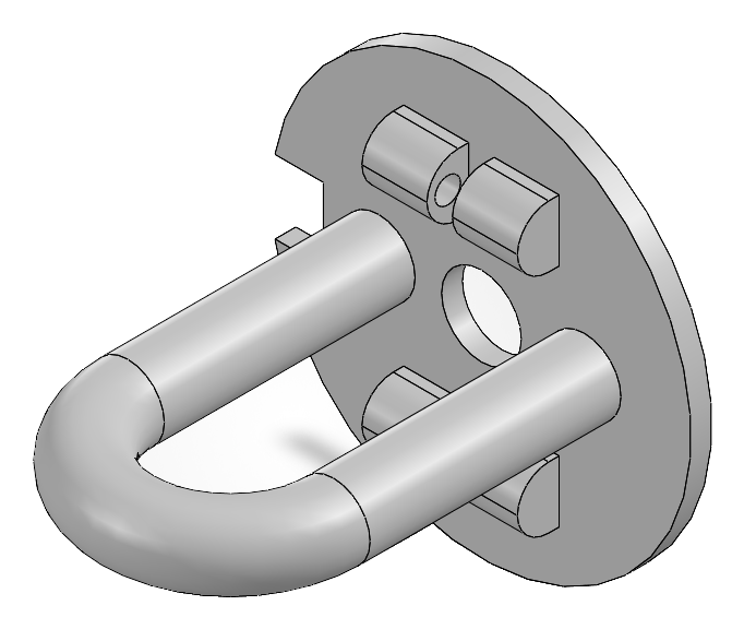
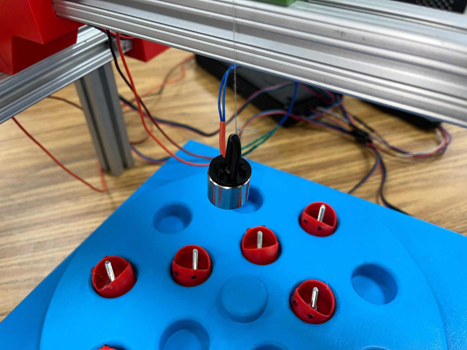
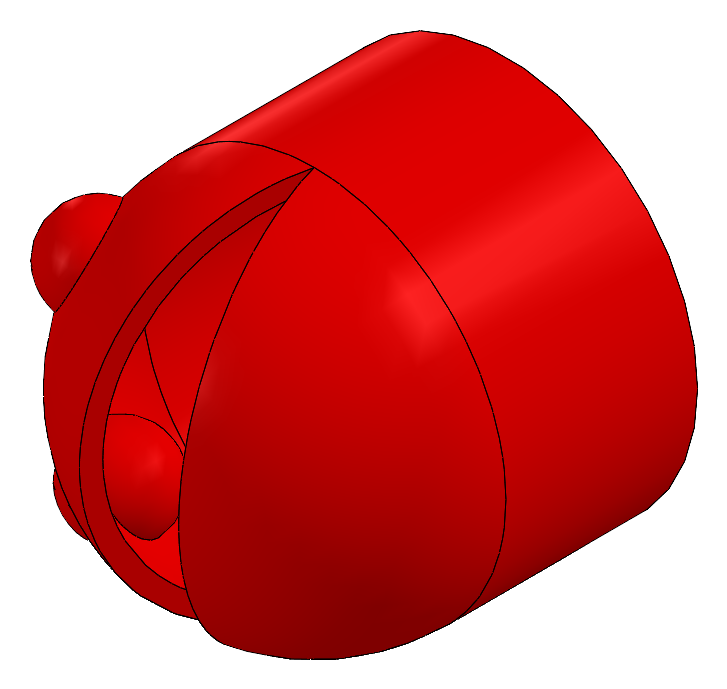
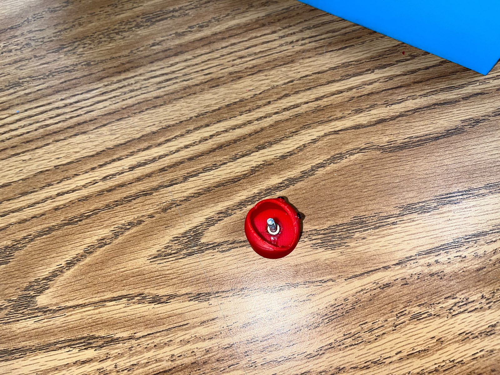
| Electromagnet holder | The end effector: holds the electromagnet at the bottom of the Z axis |
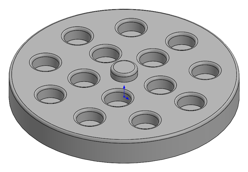
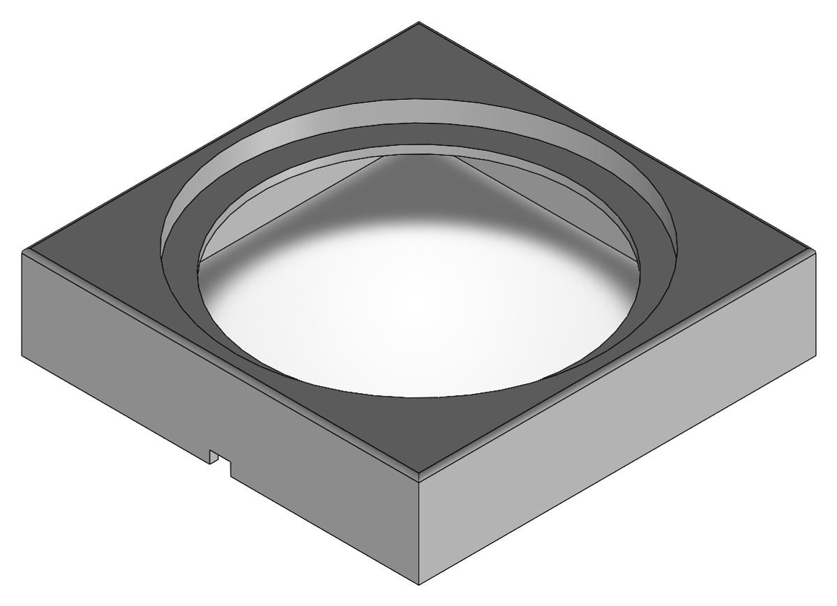
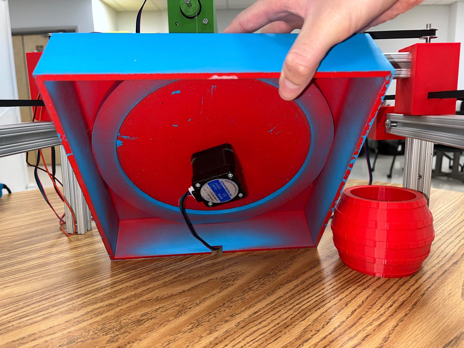
| Rotating plate and foundation | A turntable with 14 fish pockets, driven from below by the plate stepper, sitting in a base |
| Fish | Game pieces, each with a steel screw for the magnet to pick up |
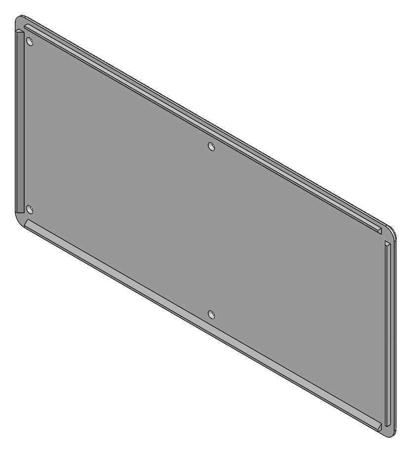
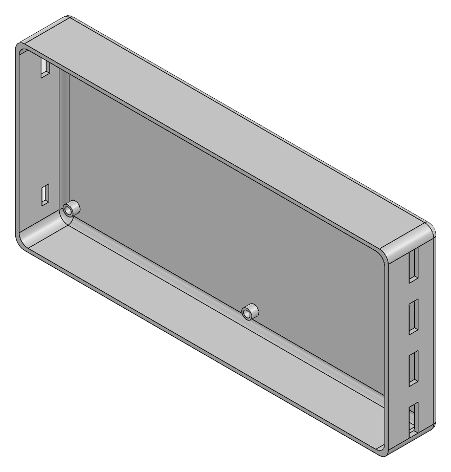
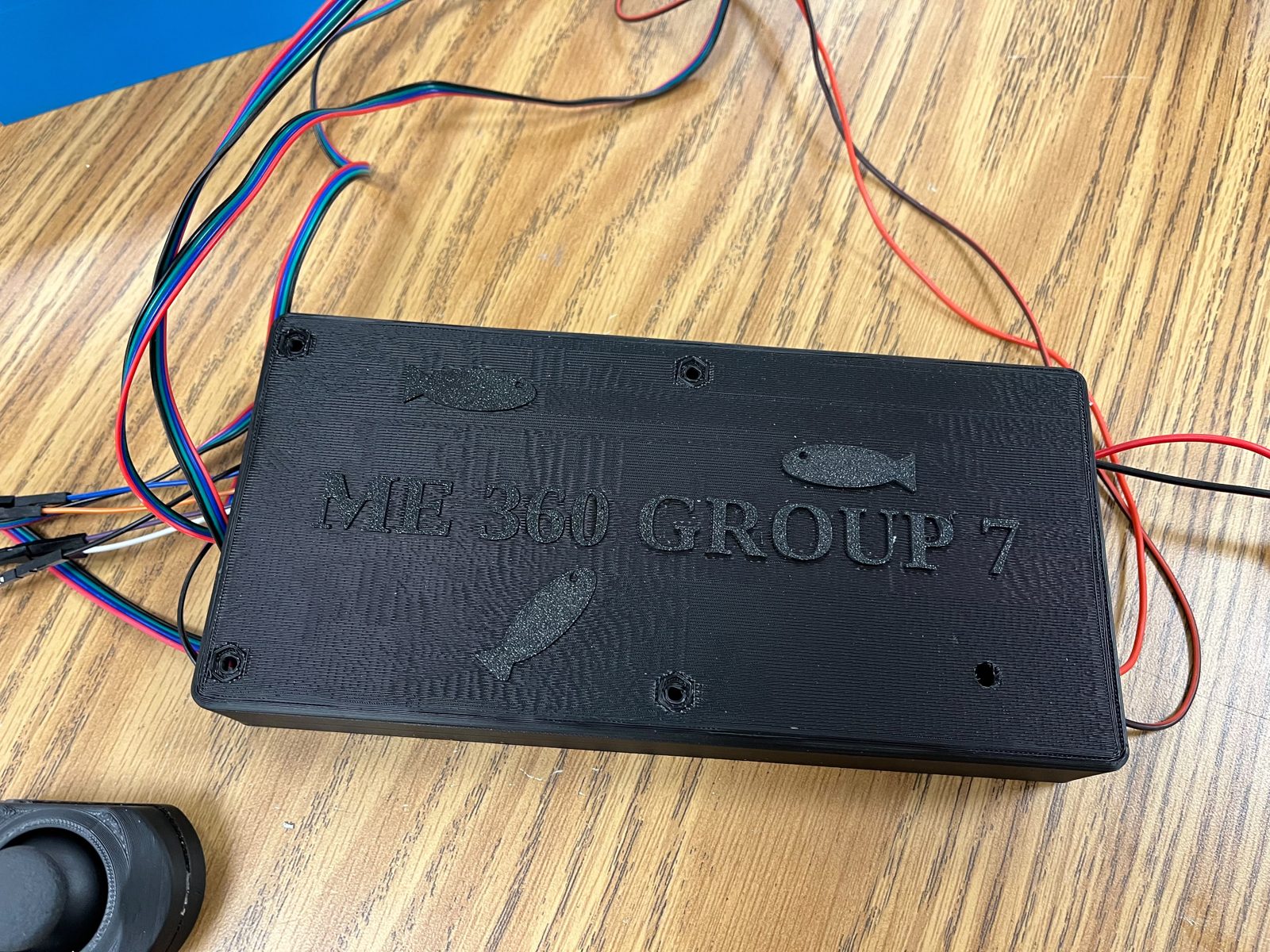
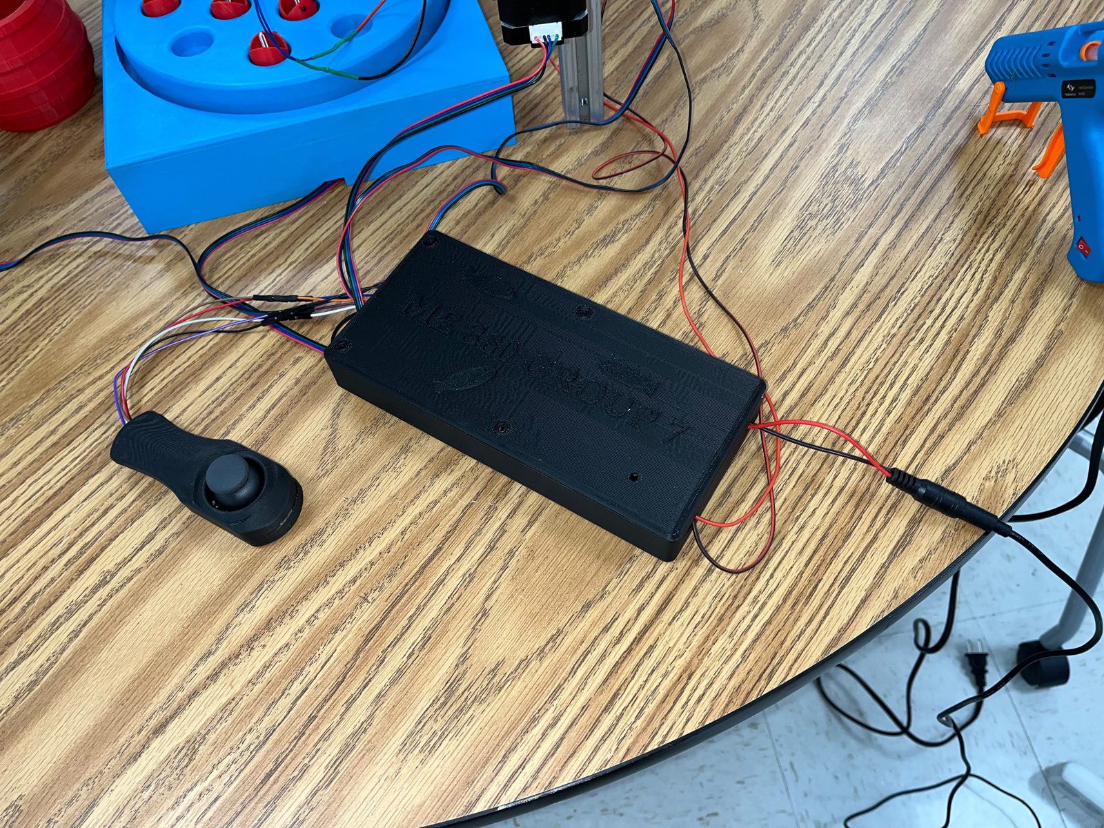
| Electronics box (top and bottom) | Encloses the MKS Base board, with slots for wiring |
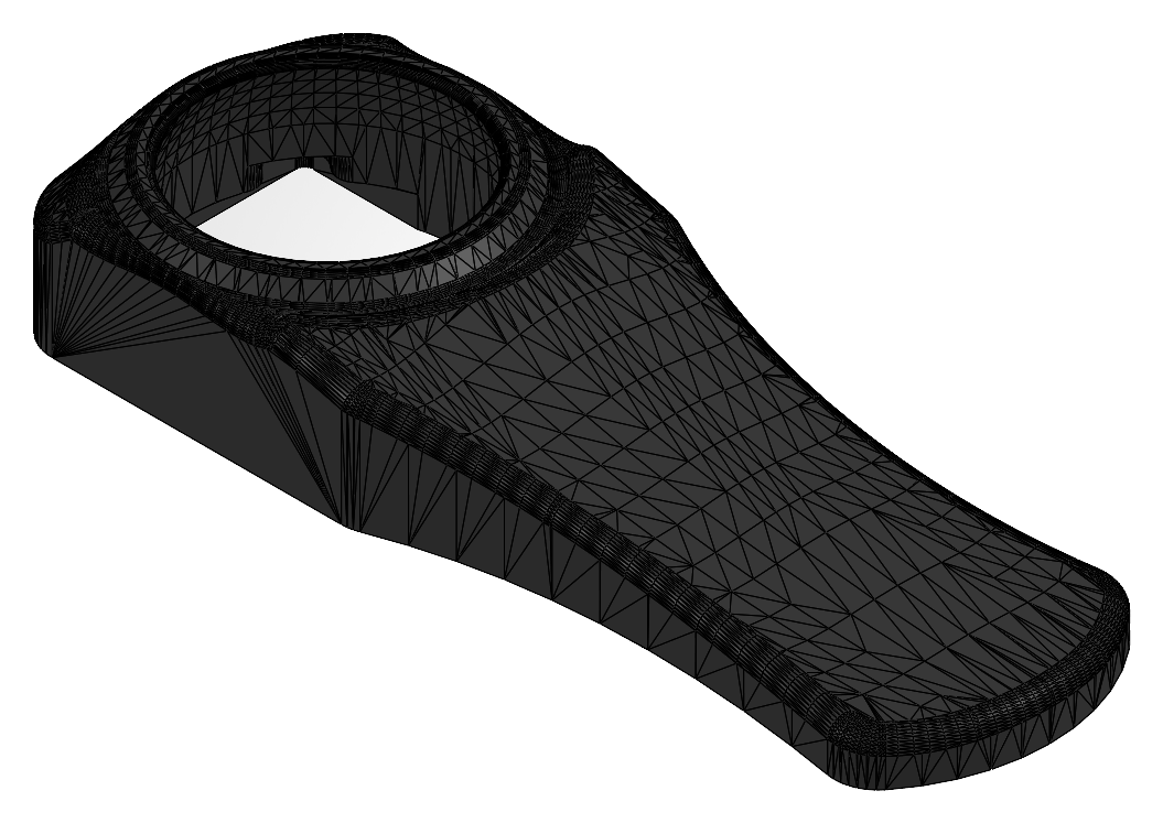
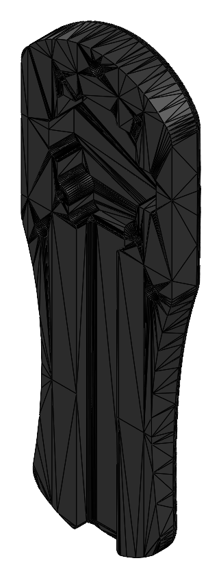
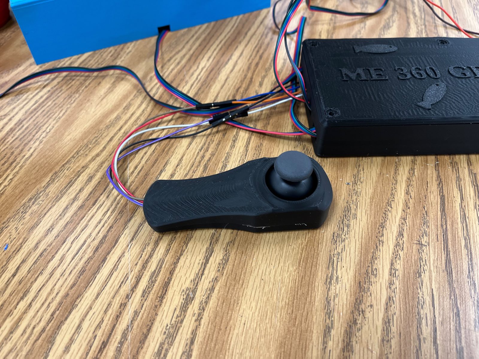
| Joystick housing (top and bottom) | A handheld shell around the joystick module |
Manufacturing
Printed Parts On Aluminum Rails
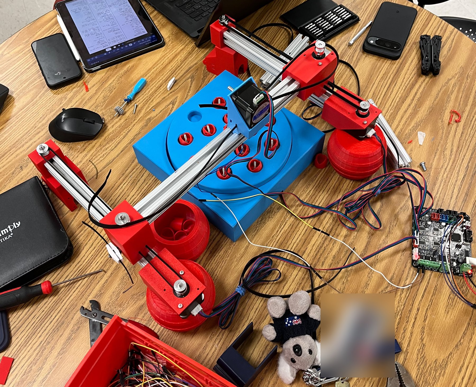
Custom parts were 3D printed; the structure uses stock 80/20 extrusion, timing belts, and off-the-shelf pulleys, all joined with screws.
| Component | How it was made |
|---|---|
| Motor holders, rail end blocks, carriages, 8020 holders | 3D printed |
| Z motor holder and electromagnet holder | 3D printed |
| Rotating plate, foundation, fish, and catch bucket | 3D printed; a steel screw in each fish for the magnet |
| Electronics box and joystick housing | 3D printed |
| Frame, legs, and rails | 1 in 80/20 aluminum extrusion, cut to length (11.5 in and 15 in rails) |
| Drive | NEMA 17 steppers, GT timing belts, aluminum timing pulleys, and idler pulleys |
| Electronics | MKS Base v1.5 board, analog joystick module, and electromagnet |
Electronics & code
From Stick To Steps
One MKS Base board (an ATmega2560 running Arduino code) reads the joystick and drives five steppers and the magnet.
| Device | Board connection |
|---|---|
| Joystick X / Y | Analog pins A11 and A12 |
| Joystick button | Pin D19, with the internal pull-up |
| X motors (two) | X and E0 driver slots, stepped together; one is reversed in code because the two motors face opposite ways |
| Y and Z motors | Y and Z driver slots |
| Plate motor | E1 driver slot |
| Electromagnet | E0 heater MOSFET output (pin D10), with a flyback diode across the coil |
We first planned to run the gantry on GRBL with G-code jog commands streamed from a laptop script that read the joystick. We switched to our own Arduino firmware so the joystick plugs straight into the board and no computer is needed during play. The firmware grew one feature at a time:
| Version | Date | What it added |
|---|---|---|
| Prototype G-code | Sep 30 | GRBL jog commands and a bench test that simulates a player |
| joystick_gantry | Oct 5 | Proportional X–Y control from the stick; a single press dips Z |
| + button | Oct 19 | Double press toggles the electromagnet |
| + rotating | Oct 19 | Long hold spins the plate |
| + timer | Oct 20 | The plate stops by itself after one minute |
| + round 2 | Oct 20 | A faster second round, then a pause and a reversed direction |
| joystick_gantry_final | Oct 20 | Round 3 with random parts, speeds, and direction changes |
How the final firmware works:
- Proportional speed. The stick is calibrated at power-on, ignores small movements near center (a dead zone), and scales speed up to 4,000 steps/s, which is 50 mm/s at 80 steps/mm.
- Smooth acceleration. Speed ramps at 8,000 steps/s² so sudden stick moves don’t stall the motors.
- Button decoding. Presses are counted on release, so the code can tell a single press, a double press, and a long hold apart.
- Z dip state machine. Down, pause, up, then idle, with X and Y locked until the dip finishes.
- Plate game. A timer steps through the rounds. Round 3’s parts and speeds are picked randomly each game, and the plate always slows to a stop before reversing.
The core of the joystick control:
// Stick reading -> signed target speed, with dead zone and proportional control
float stickToSpeed(int raw, int center) {
  int d = raw - center;
  if (abs(d) < DEADZONE) return 0;
  float span = (d > 0 ? 1023 - center : center) - DEADZONE;
  float f = (abs(d) - DEADZONE) / span;
  if (f > 1) f = 1;
  return (d > 0 ? f : -f) * MAX_SPEED_XY;
}

// Move current speed toward target, limited by acceleration
float ramp(float current, float target, float dt) {
  float maxDelta = ACCEL_XY * dt;
  if (target > current + maxDelta) return current + maxDelta;
  if (target < current - maxDelta) return current - maxDelta;
  return target;
}
Download the full Arduino sketch (joystick_gantry_final.ino)
Final assembly
The Finished Machine
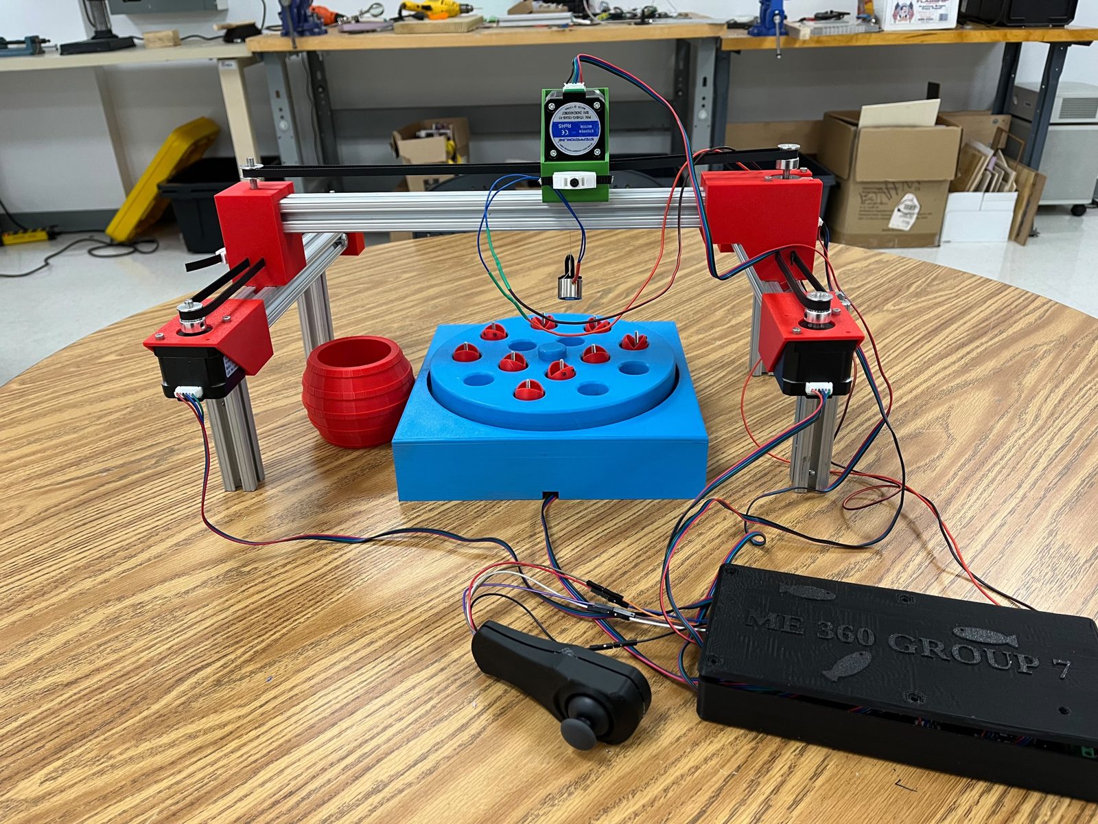
The finished gantry stands on 80/20 legs over the fish plate, with the catch bucket beside it and the controls on a cable in front.
At our final demonstration on October 21, our professor took the joystick and played the game, steering the magnet over the spinning plate.
Continue exploring